

COPRA MetalBender TD-i
Sheet Metal Application for Inventor®
Sheet Metal Lofting · Transitions · Sheet Metal Part Library · Flat Pattern Calculation
data M's Sheet Metal Technology is integrated into the Autodesk Inventor® functionality for sheet metal part design. Many powerful sheet metal features are already available for the professional designer. To enhance the existing design features and as an addition to the already existing technology for press brakes data M now also offers a solution for transitions, e.g. for HVAC applications. The COPRA® MetalBender TD·i is very easy to use and takes into account the specific requirements of sheet metal parts.
All in one
- Extensive library containing standard sheet metal parts for HVAC applications
- Automatic creation of standard transitions circular-rectangular-rounded
- Special features for designing any contours – SheetMetal Lofting
- Powerful flat pattern calculation for rounded and sharp-edged sheet metal parts with: COPRA® MetalBender Analyser·i
Quote from Mr Jim Quanci, director of Autodesk Developer Network:
“With the data M software COPRA® MetalBender TD-i, it is very easy to create multi-part transitions. You don’t have to create complex parametric sketches aligned to sketchplanes somewhere in space. And the positioning of the single parts in an assembly is also not required, it’s all done automatically. Even if dimensions have to be changed, all necessary sketchplanes, sketches and parts of the transition and existing flat patterns are updated automatically.”
Sheet Metal Part Library
The TD·i Library consists of standard parts as used in HVAC applications.
All sheet metal parts are precisely calculated on a parametric basis as are the intersections of more than one sheet metal part. You can select the parts from a clearly designed catalogue. The parameters offered are shown in sketches making classification very easy.
Previewing parameters can be switched on or off. The designer is able to work within the design context. COPRA® MetalBender TD·i has the following characteristics:
- Automatic creation of sheet metal parts
- All designed parts are fully parametric
- Automatic creation of the corresponding assembly
- Flat pattern calculation for each individual part
- All parameters of the flat pattern calculation for each individual part are pre-set.
For example, all kinds of combinations of intersections concerning cylindrical parts and cone can be created with the standard transition command. The TD·i Library is ready to use from the very first minute due to its easy handling, correct parameter settings, automatic creation of sheet metal parts and pre-set calculation parameters. All this results in a very short amortisation period.
The following parts are available:
- Segment elbow
- Transition with offset
- Cylindrical pipe with rectangular branch
- Dished boiler end with horizontal branch pipe
- Ventilator cowl
- Conus with cylinder
- Pyramid with cylinder
- Pipe branch with cone
- Pipes
- Dished boiler end with circular base
- Pipe with oval branch
- Transition
Parametric Standard Transitions
For parametric transitions, there are basic contours like circle, rectangle and filleted rectangle available, which can be combined with the required dimensions.
Depending on the defined cut positions, different parts can be obtained, all automatically positioned in an assembly.
Sheet Metal Lofting
Step 1: Design of boundary contours
First the two boundary contours (2D contours) are created with Inventor® functionality.
The following parameters can be defined:
- Selection of the boundary contours
- Definition of the cutting gap width
- Position of cutting gap on contours
- Standard setting for number of bending edges of an arc
- Automatic division of contours, e.g. of a circle
Step 2: Bending lines
In the second step the user determines the positions of the bending lines. The corresponding elements are clearly shown in a dialog box and can be modified at a later stage.
Step 3: Calculation of 3D solid
A 3D solid is now calculated according to the defined parameters.
The following definitions can now also be made:
- Material thickness (sheet metal thickness)
- Creation of a surface or solid model
- Definition of direction into which the solid is to be extruded
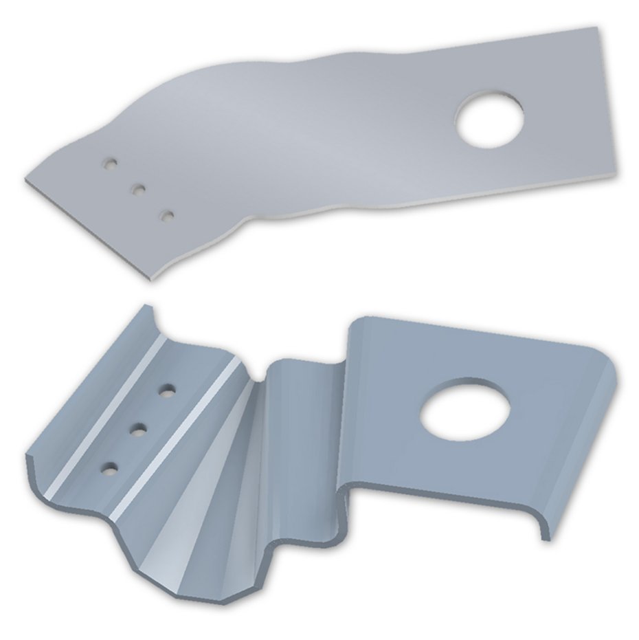
Result:
- Bendable part according to sheet metal know-how and technology
- All essential bending lines are included
- Reworking with Inventor® possible
- Flat pattern calculation with CMB Analyser·i
With the data M software COPRA MetalBender TD-i, it is very easy to create multi-part transitions. You don’t have to create complex parametric sketches aligned to sketchplanes somewhere in space. And the positioning of the single parts in an assembly is also not required, it’s all done automatically. Even if dimensions have to be changed, all necessary sketchplanes, sketches and parts of the transition and existing flat patterns are updated automatically.